I wanted to be able to flip a switch. turn a knob, or push a button.
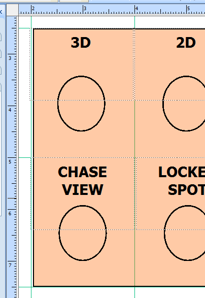
Rather than making multiple panels, these switches and buttons would be labeled, grouped by function, and aligned to a grid on a large panel.
I had an old IBM ThinkCentre collecting dust, so I thought I could put a bunch of switchs on one of the side panels. It gives me 14" wide by 15" tall to work with.
Since most of the spec drawings for the switches and buttons that I need to purchase are in metric, I went metric too giving me 36 cm by 38 cm.
Each switch will get 2 cm by 2.5 cm on the switch panel.
When a key is pressed on a keyboard a connection is made between two terminals on the circuit board. There is a top layer and a bottom layer that make contact in specific spots when a key is pressed. Here's the Dell SK-8185 keyboard I took apart:
Each circuit will hit multiple buttons. The top layer connects to the circuit board in the area highlighted in yellow. The bottom layer connects to the circuit board in the area highlighted in blue.
The contact points are labeled on the circuit board. The top contacts are labeled with X's, the bottom layer contacts are labeled with Y's. By making a closed circuit between an X and a Y, we send a keypress. For example, putting a jumper wire between X3 and Y5 sends a "j" to the computer.
Here, I am attaching solid Cat-5 to the circuit board. I drilled through the circuit board with a Dremel, inserted the bare wire and soldered the connections.
I am using 4 Cat-5 pigtails (maked 0-4). This is how I connected them to the keyboard circuit board:
Here's me trying to work out which keys get sent when you close each X and Y combination:


No comments:
Post a Comment